!MY DRAWINGS ARE NO LONGER FOR SALE!
Welcome to the
technical drawings and project
by the Fokker-Team-Schorndorf
for the
ENGELS E3
This project, designated as Engels E3, is the attempt to create a most authentic reproduction of the famous Fokker D.VII single seat persuit fighter of WWI.
The aircraft will eventually be part of the realisation of our Unique Flying Museum Dream

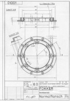
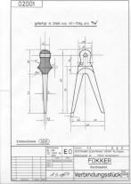
To see the sample drawings, click at them.
Information
Sheet No. II
Construction Drawings for the
ENGELS E3
Dear Sir or Madam,
Thank you very much for your
interest in our ENGELS E3 project.
The Fokker-Team-Schorndorf
is developing a complete set of construction drawings for this aircraft. The ENGELS E3 is
a reproduction of the Fokker D.VII which was originally designed in 1918 by the
engineering staff at the Fokker Flugzeugwerke G.m.b.H. Schwerin/Mecklenburg for use as a
manoeuvrable dog fight single seater.
As you can judge from the
enclosed sample drawings, our drawings are documents of the highest German standard
quality and must in no way be confused with the average drawings for
"home-built" aircraft which are available anywhere at low cost.
The drawings set available from us is based on the results of long yeared historic researches and redesigning of the type. Every little detail was checked several times by us about being historic correct. The Fokker-Team-Schorndorf also did work together with well reputated historians all around the world. Further similar aircraft by the same designers which are today preserved in museums world wide have been carefully measured, photographed and studied. Here are planes like the Fokker E.III, the Fokker D.VII itself or the Fokker D.VIII. Since no complete original set of construction drawings did survive until today (at least not to our knowledge), the redesign is based upon the above mentioned comparison with other Fokker types and their measurement as well as on many small parts of original Fokker works drawings, documents of the Prussian Army, sketches, texts and countless historic photographs. The Fokker-Team-Schorndorf did carefully work from the point of view of the historian and not from the commercial one. The drawings have been also made in this way. The main aim of the work was to preserve the knowledge about the structural design of the aircraft. If you decide to work from these plans, you will be able to construct a full size reconstruction of the airplane made famous by many leading German fighter aces like really built and flown by the Fokker Works themselves in the war time year 1918. Of course this judgment is based on our current stand of knowledge about the original plane
!!!NOTHING HAS
KNOWINGLY BEEN REMOVED, ADDED OR CHANGED!!!
Furthermore you will support
further historic researches by the Fokker-Team-Schorndorf through the purchase of these
documents.
The quality of the sample
drawings enclosed speaks for themselves. Wherever possible the separate parts have been
drawn in 1/1 scale.
The sizes of the sheets of
the set differ between Din A4 and Din A0. Most of the drawings are covered on Din A3
sheets. For better understanding drawings of single parts only do show one part.
We have been endeavoured to
keep alive the origin stile of the drawings made at the Fokker Flugzeugwerke G.m.b.H. The
scale of the shown parts differ between 1/20,
1/10, 1/5, 1/3 and mostly 1/1. The set includes one big sheet in about Din A0 size. This
one shows the fuselage frame in 1/5 scale. All drawings will be delivered folded according
to DIN (German industrial norms) regulations. Each sheet is protected by a transparent
plastic cover. The complete drawing set consists of approximately 250 drawings.
However you may decide, we
whish you that you will be able to turn your will into a fact and all the luck and all the
fun during construction.
faithfully
The
FOKKER-TEAM-SCHORNDORF
Adresse, Address:
Fokker-Team-Schorndorf
Achim Sven Engels
Schillerstrasse 22/4
73547 Lorch - Germany
Tel.0049 / 71 72 / 91
55 77
E-Mail: engels@collectors-edition.de
____________________________________________
How to Work
from the
Construction Drawings
Explained at the example of the ENGELS E1
written by Achim Sven Engels
A.)
The System of the Tidiness.
To understand completely the conception of tidiness of
these manufacturing documents it is necessary to know that an aircraft is split up in
several units which will be called by using the German word "Baugruppe"
(construction units). These "Baugruppen" are the same for every plan set by the
FOKKER-TEAM-SCHORNDORF. Which they are and what they do consist of will be explained in
the following:
Baugruppe
100 The
Motorization:
Engine cowling,
firewall, engine mountings and gasoline and oil tanks.
Baugruppe
200 The
Fuselage:
Fabric covering,
fuselage frame, wing mounting, cowlings and cross bracings.
Undercarriage,
axle fairings and wheels.
Stabilizer and elevator.
Back Finn (not
in existence on the Dr.I) and Rudder.
Wing spars,
ribs, airfoil, all wings, the interplane struts and ailerons.
Control systems,
cockpit floor, seat and belts and the instruments.
Machine gun
mountings, ammunition belt feed and ammunition boxes.
Tubes of the main system and total aircraft
views.
Baugruppe
000 The
Aircraft:
General common
construction instructions and bracing orders (degree of incidence at the wings).
B.) The Manufacturing Documents
After we did learn how an aircraft is split up in
different units we will now start to familiarize with the components of the manufacturing
documents.
1. The drawings,
2. the bills of
material,
1.
The Drawings:
The drawings are also splitted into three groups. The
first group shows every "Baugruppe" completely assembled with the dimensions
given. The second group is formed by the separate parts drawings. Each separate part did
already get in the first group of the drawings its own part number. The drawings of the
separate parts do show them with all dimensions given that are necessary to construct it
and are also mostly kept in 1/1 Scale. The third group of drawings are the assembly
drawings. They show how to connect all parts and/or components. This third group only
gives the really important dimensions.
Each drawing sheet has got its own number of course, too.
These will be three-digit for the Fokker Dr.I. The first number of these is the number of
the "Baugruppe" whilst the last both digits are the ongoing number of sheets in
this "Baugruppe".
If in any group of the drawings something will be referred
to another drawing, this will happen through the according sheet number shown in an oval
border.
The drawings of the parts which will require steel tubing
to manufacture do have a table in which it is stated how much of what size is needed.
2.
The Bills of Material:
Each Baugruppe has got its own list of material. Under the
separate part number given in the drawings you will find each part in the list of
material. The list of material tells you how often a part will be needed, how it is named
and which materials are necessary to construct it and furthermore what sheet number covers
the closest drawing of the part concerned.
Example:
You are working at the construction of the elevator and be
trying to find closer information about the construction of the hinges. The complete
drawing of the elevator shows you that the part number of the hinge is 4230. Now you will
take the bill of material of "Baugruppe" 400 and since everything is shown in
numerical order you will find the part number 4230 relatively fast and without problems.
The most important information are given here. You will
learn from the bill that there are three hinges required, that the most needed material
will be mild steel sheet of a thickness of 1,5mm and last but not least that the closest
drawing of part number 4230 is covered on sheet No. 403.
But not everything can be learned that easy from the bill
of material. There will be not mentioned that part number 4230 do consist of two parts. On
the first hand there will be needed the steel sheets and on the second hand there is a
part of brass tube which will be the hinges bearing. This information is given in the
separate parts drawing of the hinge only.
3.
The Description of the Construction:
Up to now there are no descriptions available.
Some photographs of the project under construction:

A lot of hand crafting! Here is the making of the radiator shutters.

For comparision: Some shutters finished.

Welded joints in the fuselage frames. Here a close up of the forward undercarriage leg attachment point.

Airscrew under construction.

Finished airscrews alongside those still in the making.
Hand made fuel tank fillers.

Fuel tank during pressure testing.

Ammo box and empty belt box mounted to the airframe.

The first weapon in place.

Wing spar during construction.

Load test with a wing rib. 520 kg and still no failure. As you can see, we then ran out of space for more sand bags...

Wing under construction.

Upper wing.

Wing construction.

Our official construction supervisor for this LBA registered Experimental aircraft, Hartmut Sammer, obviously happy with the workmanship.

First fitting of fuselage and wings.

Pulley brackets of the ENGELS E3 compared with the factory drawing of the same part in the Fokker D.VII..

